Siemens NX
Design Guidelines
CAD standardization as the basis for streamlined and automated processes.
neoapps | Themes
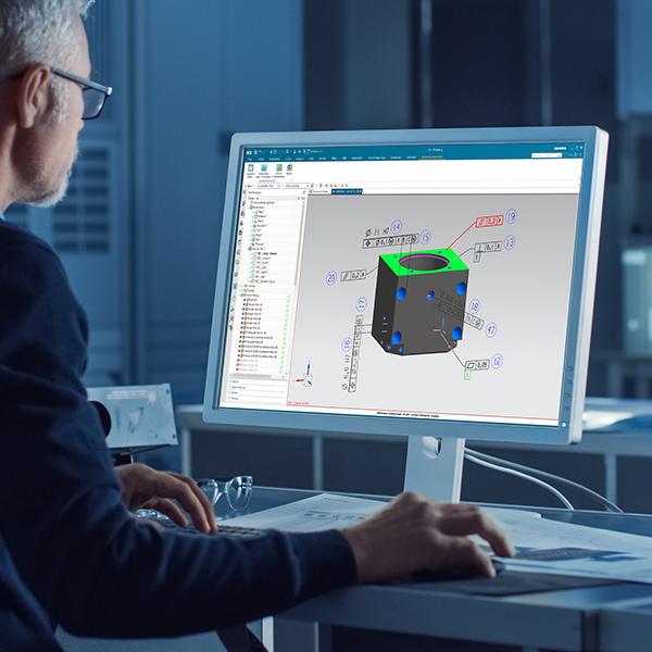
A CAD system like Siemens NX provides the designer with a wide range of tools and functionalities in order to cope with the daily tasks and challenges of a designer. Often, many paths lead to the goal using different design approaches. However, designers usually do not work in isolation, but act in teams that not only span departments but sometimes even entire continents. So how do you prevent diverging design approaches in 3D models and 2D drawings? And how can you ensure that only the “best” approaches and methods are used by the design team? This is where design guidelines come into play.
What are design guidelines?
Design guidelines are all methods and company standards that a designer has to take into account when creating CAD data. The design guidelines thus represent an explicit knowledge base for engineering, which defines and explains best practice approaches and is made available to all employees in the product development process. Following design guidelines can reduce errors and improve design quality.
Why are design guidelines important?
Uniform and company-wide design guidelines in CAD are of outstanding importance, because automation of the process chain in product development is unthinkable without standardization. Subsequent processes are usually based directly on the design data, which is why uniform standards are essential. The advent of Model-Based Definition further reinforces this trend.
The existence of company-wide guidelines has the following effects, among others:
- Cost reduction
Uniform design guidelines help identify errors early in the development process. Complex and expensive corrections in later phases of the product life cycle can thus be avoided. - Machine readability
Design guidelines make CAD models for machines or software applications consumable in subsequent processes. Above all, metadata such as attributes play a key role, as they allow for consumablity of the 3D model downstream. But formal specifications such as the assignment of layers or naming conventions for sketches or views are also of crucial importance. - Best Practise
Design guidelines reflect best practice approaches. These best practice approaches were systematically identified and evaluated as part of the definition of the design specifications. With these best practice approaches, productivity can be kept high along the entire process chain. However, this presupposes that the methods on which the guidelines are based are always kept up to date. The methods and guidelines should be updated and in the course of a Siemens NX release change project. - Compatibility with Customers and Suppliers
Many companies do not act autonomously, but are often embedded in a complex system of suppliers and customers. A common language is required so that CAD data can be interpreted without any problems and can be used for downstream processes. Design Guidelines represent such a common language and allow for a coordinated collaboration between OEM, customer and supplier.
Standards in CAD are essential for the digitization of product development. Automation in the subsequent processes is only possible through standardization in the design. For this reason, the creation of company-wide design guidelines is not just optional, but an absolute must for every innovative company.
Tim Behnke
neoapps, CEO
Examples of Siemens NX Design Guidelines
Classic examples of design guidelines include the following:
- Material Information
- Symbols and Symbol Libraries
- Fonts and Styles of PMI and Dimensions
- Layer Occupancy of Bodies, Sketches, PMI, etc.
- Reference Sets
- Arrangements
- Drawing Templates
- Drawing Frames
- Assembly Structure
- Color Settings
- Synchronous Methods
- Metadata
- PMI Structure
- Neutral Formats
- Large Assembly Management
- Weight Management
- Naming Convention
How are design guidelines created?
The creation of design guidelines usually follows a multi-stage process and depends largely on the initial situation of the respective company context. So it makes a big difference whether the design guidelines are introduced “on the green field” (e.g. in startups) or whether there is already a history (e.g. in the course of the conversion to a new CAD system).
In most cases there is already a certain history or an informal standard. In these projects, guidelines are primarily “brought to light”, explicitly recorded and then refined and expanded to include best-practice methods.
In most cases, the process for developing company-specific design guidelines goes through the following five stages:
- Status Quo
In this phase, the current way of working is recorded in the status quo. The survey is carried out through targeted interviews of the key users in construction. Proven and established practices and methods often already exist in individual departments or project teams. In this phase, these are brought to the surface and explicitly recorded and analized. - Requirements
In the next step, the goals of the project are defined. Design guidelines are only a means to an end, not an end itself. For this reason, the definition of the goals is a multidisciplinary process in which both the design and other departments from the downstream process chain must be involved. For example the manufacturing department form the CAM process chain or quality assurance for CMM. CAM and CMM usually consume CAD data directly, which is why thei significantly influence way CAD models have to be created and specified. The involvement of important suppliers or customers have to be taken unto account in this phase. - Development of methods and design standards
Based on the defined goals, best practice methods are developed and evaluated in the next step. How are holes created and specified in CAD? How are large assemblies built, structured and simplified? Which templates and symbol libraries should be used? NX Open programs are also conceptually recorded in this project step. In this project step, the foundation for the productivity of the design as well as the degree of automation in the product development is laid. - Documentation
After the CAD methods and guidelines have been successfully defined, all design guidelines are documented in the form of a digital manual. The design guidelines are usually integrated into an in-house Wiki so that the design guidelines are available regardless of location and can be viewed at any time. - Training
In order to disseminate the guidelines more widely, the last step is the comprehensive training of users in the design and engineering department.
The Design Guidelines Manual
Enforcing best practices across the entire organization
The design guidelines manual is the systematic documentation of design guidelines for everyone involved in the creation of CAD data. Today, design manuals are primarily managed digitally. They are usually embedded in an interdisciplinary company wiki. The manuals also provide the basis for the creation of checks of various design validation tools for Siemens NX such as the CheckSuite.

Automated product design validation
Software-based validation of CAD-data for streamlined processes.
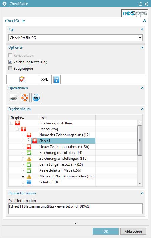
If you want to validate your CAD data in an automated fashion there is no way around a product validation software. The CheckSuite is such a software. It allows the designer to check the product data at the push of a button.

Our services regarding Design Guidelines

Methods Workshop
Innovative methods that fit your needs.
The creation of standardized design guidelines requires a thorough analysis and consideration of the methods. We will help you in a workshop to find the right methods and standards for your company.

Design Guidelines
Digital design manual for standardized guidelines.
The transfer of design methods into a company-wide manual is not an easy task. That is why we are happy to support you in creating the (digital) manual with our best practice approaches.

Customized Solutions
Custom made add-on solutions for more standardization.
Do you want to realize your own ideas and make them the company-wide standard? We develop tailor-made add-on solutions and applications that help you standardize your design.
Our solutions regarding Design Guidelines

TE-Toolbox
Standardization with Technical Elements.
Technical Elements are recurring design features which are inserted into the model in a highly standardized manner. In contrast to UDFs or feature templates, TEs contain a lot of meta data that can be used to automate subsequent processes.

CheckSuite
Automated Product Design Validation.
The CheckSuite is a solution that allows you to validate your produc design data in NX at the push of a button. This makes sure that company standards and methods are used throughout the company. Subsequent processes can be automated more reliably and without manual rework.

Representation
Handling Large Assemblies in NX.
NX Representation is a basic technology for working with large assemblies. This speeds up loading and closing time in NX. With this solution, you automate the generation of faceted representations in your design and thus ensure more efficiency when dealing with large assemblies in the company.
Do you have more questions regarding Design Guidelines in Siemens NX?
Talk to our experts and learn more about design guidelines for Siemens NX
